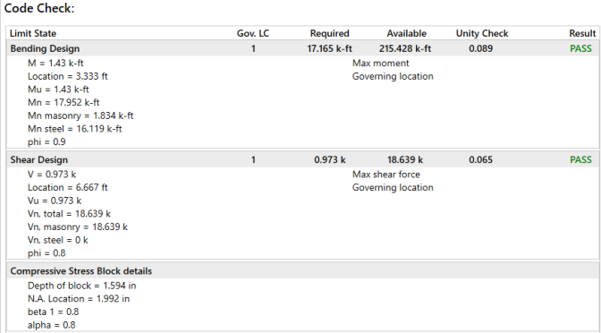
Masonry wall results are presented in the wall results spreadsheets and the detail reports. Results are reported on a region by region basis. In addition, the code checks for lintels spanning openings are reported separately.
For general wall panel information, see the Wall Panels topic. For information on masonry design rules, see the Masonry Wall - Design Rules . For masonry wall modeling procedures, see the Masonry Wall - Modeling topic. For masonry calculation considerations and code references, see the Masonry Wall - Design topic.
Note:
The information on this spreadsheet is present on
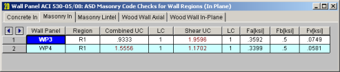
The In-Plane results are intended to provide the code checks relevant to shear wall behavior for the wall.
For ASD codes the Combined UC entry gives the code check due to axial force plus in-plane bending. The Shear UC will show the code check for shear effects. A value greater 1.0 for either of these values would indicate failure.
For Strength codes the Axial UC, Bending UC and Shear UC gives the individual code checks for each of these limit states.
The Fa or Pn*Phi reports the allowable axial stress or axial capacity.
The Fb or Mn*Phi reports the calculated allowable bending or moment capacity for the region.
The Fv or Vn*Phi reports the calculated allowable shear stress or Shear Capacity for the region.
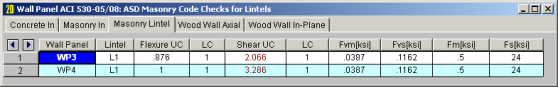
The Lintel results give the results for the masonry lintels that span over user defined openings in the wall. They can also be viewed by looking at the detail report associated with each opening.
The Bending UC entry gives the code check due pure flexure of the Lintel. Axial force is not considered in this code check at all. The Shear UC gives the code check for shear. A value greater 1.0 for either of these values would indicate failure.
The Fm and Fs or Mn*Phi reports the calculated allowable bending stress or moment capacity for the region.
The Fvm and Fvs or Vn*Phi reports the allowable shear stress or shear capacity.
The last two tabs of this spreadsheet contain results for Masonry Wall reinforcement.
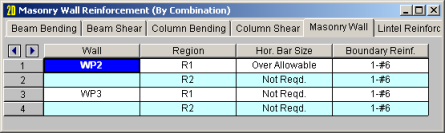
The Masonry Wall tab displays analysis results for the reinforcement of each region defined in your masonry wall.
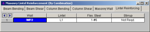
The Lintel
The detail reports show the overall geometry, analysis and design for the individual regions of the wall panel. The report also shows envelope diagrams for the forces and moments in the region.
Three basic types of detail reports are provided: Wall Summary, Region and Opening.
Once you have a solved model, the detail reports become available. They are accessible in two ways:

 button on the
 Note:
Once the detail report window is open, you will see a dialog area at the top.
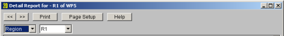
These options control the display of the Detail Report:
 - The arrow buttons allow you to scroll quickly between the different wall panels in your model.
 - This button will allow you to take a snapshot of the current detail report you are viewing so that it can be added to a report. View the Printing topic for more information.
 - The first drop down list allows you to select between individual Region and Opening (Lintel) results and a summary of the entire Wall. Below we will explain the importance of each of these sections.
This report gives an overview of the wall, a summary of the controlling code checks and deflection information. This report also displays information about the wall
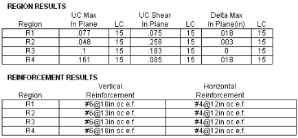
The Region Results section gives the tabulated results of all regions in the wall for in plane design axial/bending, shear and deflection for quick reference. You can view the individual region reports to get a more detailed explanation of these values.
The Reinforcement Results section gives the reinforcement results for each region in the wall.
The Lintel Reinforcement Resultssection gives the label and reinforcement for any lintels in the wall.
You can click any of the In-Plane region sections in order to expand the section and view additional details pertinent for that specific region.
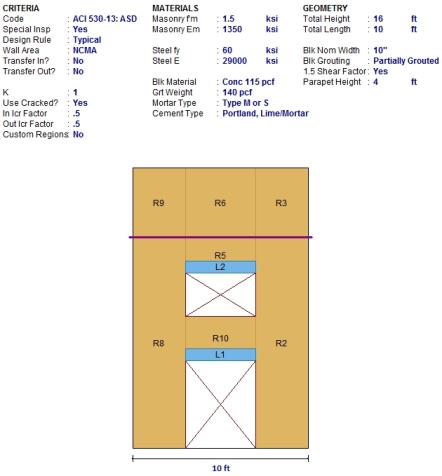
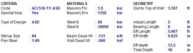
The top section of the detail report echoes back the input information used in the design of the wall region or lintel. This information is summarized below:
| Criteria | Description |
|---|---|
| Code | Gives the code used to design your wall panel. |
| Special Inspection | Indicates whether special inspection is required for your wall. Special inspection is normally required for all walls designed to the MSJC / IBC codes. The UBC 1997 is the one code that allows the user to decide whether special inspection is required. |
| Wall Area | See the Wall Design Rules - Masonry Wall spreadsheet |
| Horizontal Bar Size | Indicates the bar size to be used to resist shear forces. |
| Vertical Bar Size | Indicates the bar size to be used to resist the tensile stress due to moment. |
| Number of Tension Bars | Indicates the number of vertical bars present in the boundary region of the wall. |
| Effective depth | This gives you the distance from the compression face of the wall to the centroid of tension reinforcement. |
The Materials column can be mostly modified under the Materials button on the Data Entry toolbar.
The Geometry column gives the basic geometry of the wall. Block grouting and the grout spacing are specified in the Wall Panel Editor. The block nominal width is input under the Wall Design Rules - Masonry Wall tab.
The
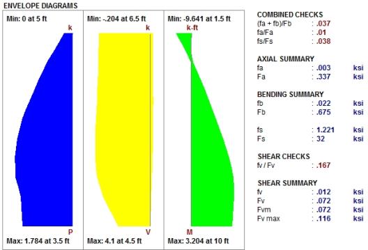
The Combined Check Summary gives maximum overall code checks considering the effects of both bending and axial stresses. This section is not reported for MSJC strength design.
The Axial Summary and Bending Summary give the values used in the axial and flexural code checks at the location which controls the combined check (fa+fb)/Fb for ASD design.
For ASD design, the maximum bending stress in the flexural reinforcement is reported as fs, and the allowable steel bending stress as Fs. These values are given for the Load Combination and section that produce the maximum code check (fs/Fs).
The Shear Summary reports the maximum shear demand on the beam as fv or Vu. The allowable shear stresses are then reported as Fvm and Fvs, where Fvm is the allowable of the masonry alone and Fvs is the allowable considering the effects of the shear reinforcement.
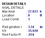
| Axial Details | Description |
|---|---|
| Maximum Axial Force | The maximum axial force in the wall. |
| Location | The location along the height of the wall which produces the maximum axial force. |
|
|
The load combination that produced the maximum axial force. |
| Radius of Gyration (r) | The out of plane radius of gyration for the wall. |
| h/r | Slenderness ratio of the wall |
| Reduction Factor R |
This is the slenderness reduction portion of equations 8-13, 8-14, 9-11 and 9-12. |
Click the Bending Design section to expand the section and see more details.
Ultimate Strength Design |
Working Stress Design (ASD) |
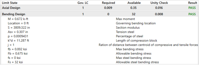
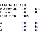
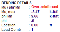
| Bending Details | Description |
|---|---|
| Maximum Moment | The maximum moment in the wall. |
| Location | The height of the wall where the maximum bending moment is located. |
|
|
The load combination that produced the maximum bending moment. |
| Section Modulus (S) | The uncracked section modulus. This is based on the effective thickness and the length of the wall. |
| Tension Steel Asv | The area of tension steel in this region of the wall panel. |
| Percentage of Steel (p) | The reinforcement ratio in this region of the wall panel. |
| k*d | The length of the compression block. |
| j |
The ratio of the distance between the centroid of the compressive and tensile forces (j). |
| a | Depth of compression block. |
| c | Depth of Neutral Axis. |
| d | Depth of section from compression fiber to centroid of tensile reinforcement. |
See the Masonry Wall - Design topic for more information.
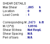
| Shear Details | Description |
|---|---|
| Moment | The moment corresponding to the maximum shear check is reported along with the M/Vd ratio. |
| Shear Steel Area |
The shear area per bar (Av) is reported along with its center to center spacing and the perimeter of the reinforcing bars used for the calculation of allowable bond stress.
|
| Shear Bar Spacing | The spacing of shear steel in the region of the wall panel. |
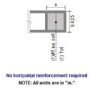
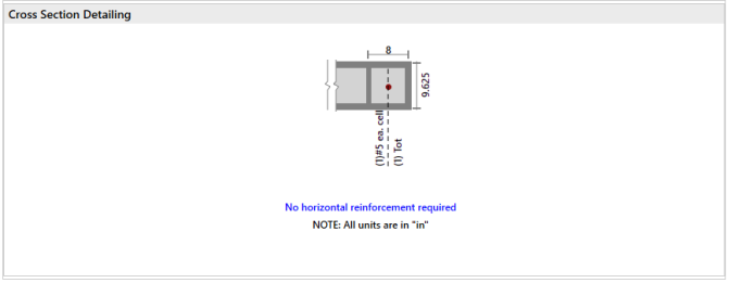
This section of the detail report is meant to provide a visual confirmation to the user of the boundary zone width and reinforcement.
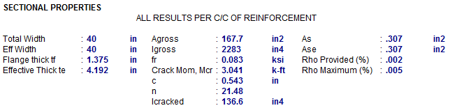
The center to center distance between reinforcing Total Width and the Eff Width (which accounts for partially grouted walls) are both reported in this section. The Flange Thick tf refers to the thickness of the face shell whereas the Effective Thick te refers to the overall effective depth of the block.
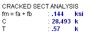
The gross area and moment of inertia are reported along with the modulus of rupture, cracking moment, neutral axis, modular ratio between steel and masonry, and the cracked moment of inertia.
The area of steel As and the effective area of steel Ase are reported, with the effective area based upon As + Pu/fy.
The gross steel ratio (rho gross) is calculated as the area of steel divided by the total area of the section.
The Rho Provided (%) is calculated as the area of steel divided by the total width times the effective depth (As/bd). This is limited to a Rho Maximum (%) value of 0.5 * rho balanced per the UBC-97 Section 2108.2.3.7. This provision was implemented in future codes as well.
The Sectional Properties gives a number of the properties used during the iterative slender wall design procedure. All of these properties are reported based on a section of wall equal to the center to center spacing of the reinforcement.
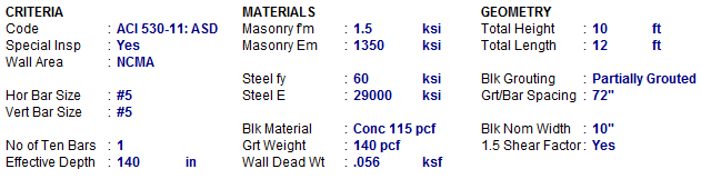
The first section of the detail report echoes back the basic input parameters (Criteria, Materials, Geometry) entered by the user. An example is shown below:
The geometry portion and the dead weight of the wall warrant further explanation
| Attribute | Description |
|---|---|
| Beam Dead Weight | This is based on the user defined density for the Lintel / Opening. |
| Wall Dead Weight | This is based on the wall self weight or the self weight of the region immediately above the opening. |
| Dist to Top of Wall | This is the distance from the top of the lintel to the top of the wall and is used in the calculation of the arching action of the lintel loads. |
| Actual Length | This is the total width of the opening. |
| Bearing Length | This is the bearing length of the lintel on either side of the opening. |
| Effective Length | The Center to Center distance between lintel supports. Assumed to be length of the opening plus half of the bearing area on each side. |
| Effective Width | The thickness of the block used to define the lintel. |
| Effective depth | Equivalent to the "d" distance, the distance from the effective compression face to the centerline of the tension reinforcing. |
| Total Depth | This is the total depth of the fully grouted portion of the lintel. |
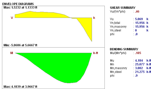
The next section of the detail report provides the envelope shear and moment diagrams as well as a summary of the code checks for the Lintel.
The next section of the detail report gives further details for the design checks performed on the lintel.
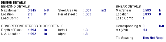

This Bending Details show the magnitude, location and load combination that correspond to the maximum moment used in the design as well as the area of flexural steel required (As) and the steel ratio (rho).
The Compressive Stress Block Details show the parameters used in calculating the strength of the lintel.
The Shear Details show the magnitude, location and load combination that correspond to the maximum shear used in the design, the M/(V*d) ratio for shear design, and the required spacing of ties (if applicable).
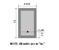
This section of the detail report is meant to provide a visual confirmation to the user of the basic geometry and reinforcement provided in the lintel.